This article provides additional information to understand the EQuIS Geotech workflows and how data are connected in the database. Specific topics include:
•Associating Projects and Tasks
•Lab Assignment Test Set Configuration
•Hydrometer Bulb Calibration Data
•DT_FILE EnviroInsite and Report Graphic Configuration
AT_MATERIAL Configuration
The AT_MATERIAL table is used to group RT_MATERIAL.MATERIAL_NAME values into groups. The AT_MATERIAL.MATERIAL_TYPE_CODE equates to a group value.
Example of AT_MATERIAL.MATERIAL_TYPE_CODE values:
•Material_Name
•Material_Graphic
•USCS_Symbol
The AT_MATERIAL.MATERIAL_TYPE_CODE values are used in the Geotechnical Collect Report.
Lab Assignment Test Set Configuration
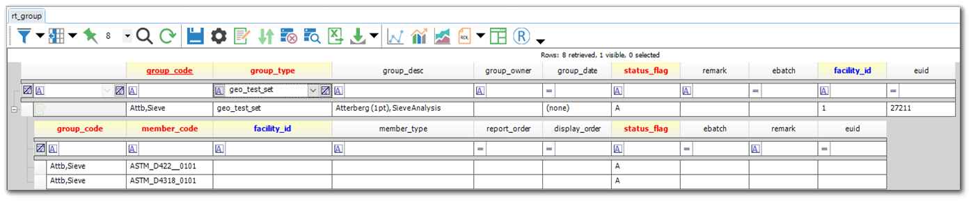
The purpose of a Test Set is to group a set of tests together that are commonly assigned to samples. Test sets are configured in the ST_GROUP_TYPE, RT_GROUP, and RT_GROUP_MEMBER tables. The RT_GROUP.GROUP_TYPE = ‘geo_test_set’.
ST_GROUP_TYPE:
•ST_GROUP_TYPE.GROUP_TYPE = ‘geo_test_set’
RT_GROUP:
•RT_GROUP.GROUP_TYPE = ‘geo_test_set’.
•A Test Set name should be assigned to RT_GROUP.GROUP_CODE.
•If a Test Set is specific to an office, then the RT_GROUP.GROUP_OWNER should be populated with the RT_COMPANY.COMPANY_CODE associated with the office. If the RT_GROUP.GROUP_OWNER is empty, then the Test Set is assumed to apply to all offices.
RT_GROUP_MEMBER:
•The RT_GROUP_MEMBER.GROUP_CODE should match RT_GROUP.GROUP_CODE.
•The RT_GROUP_MEMBER.MEMBER_CODE should be populated with the RT_GEO_TEST_METHOD.TEST_METHOD_CODE that should be part of the Test Set.
Sieve Set Configuration
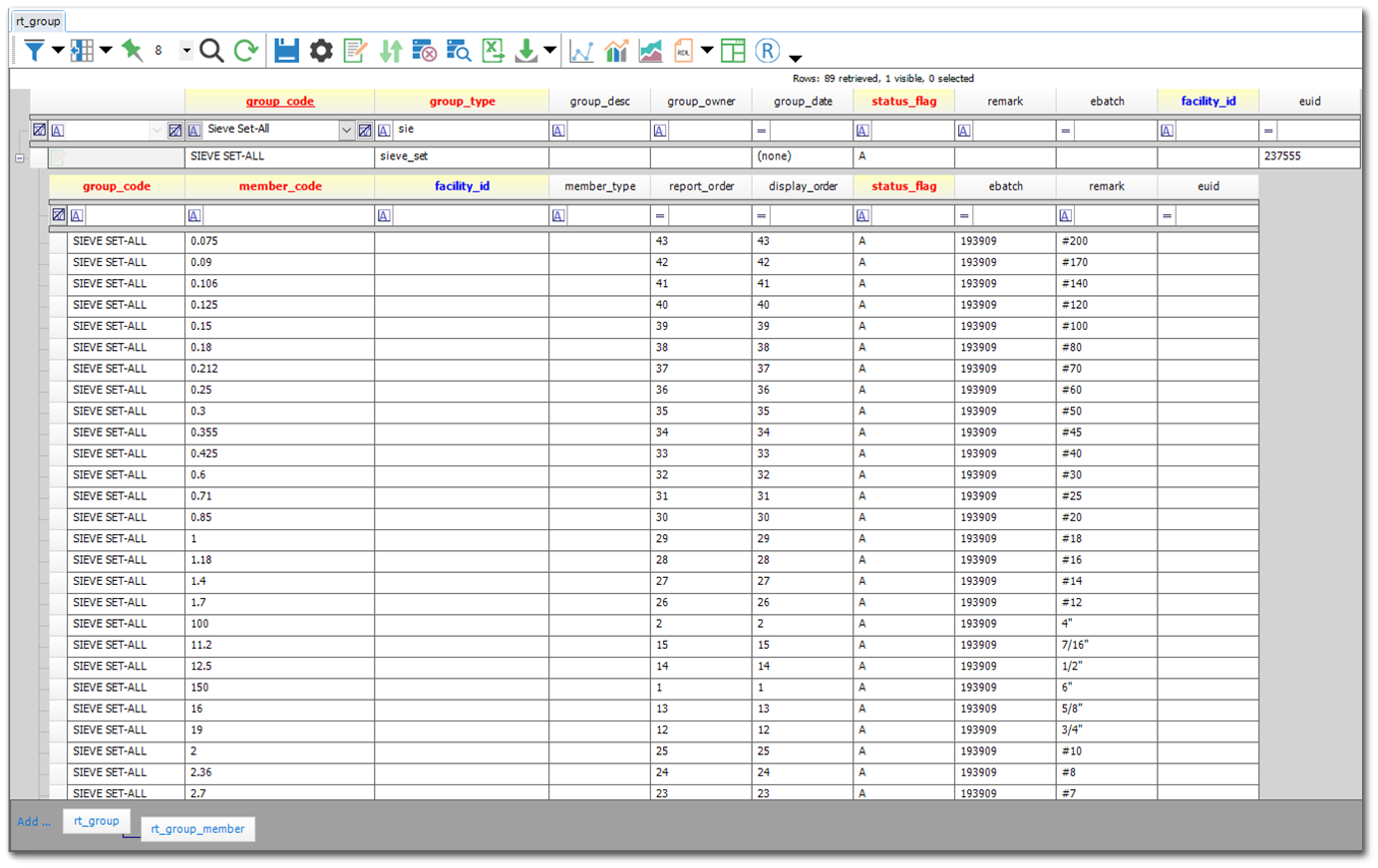
The purpose of Sieve Sets is to associate a set of sieve diameters to their corresponding sieve names. Sieve Sets are configured in the ST_GROUP_TYPE, RT_GROUP, and RT_GROUP_MEMBER tables. The RT_GROUP.GROUP_TYPE = ‘sieve_set’. The Geotechnical Collect Report references the Sieve Set values from the RT_GROUP and RT_GROUP_MEMBER tables.
ST_GROUP_TYPE:
•ST_GROUP_TYPE.GROUP_TYPE = ‘sieve_set’
RT_GROUP:
•RT_GROUP.GROUP_TYPE = ‘sieve_set’
•A Sieve Set name should be assigned to RT_GROUP.GROUP_CODE.
RT_GROUP_MEMBER:
•The RT_GROUP_MEMBER.GROUP_CODE should match RT_GROUP.GROUP_CODE.
•The RT_GROUP_MEMBER.MEMBER_CODE should be populated with the sieve diameter value (ex. 0.075).
•The RT_GROUP_MEMBER.REMARK should be populated with the sieve name value (ex. #200).
•The RT_GROUP_MEMBER.REPORT_ORDER should be populated to define the order that displays.
Note: The Collect Geotechnical Field and Lab Data Entry Template uses the defined Sieve Set values to display the appropriate Sieve Name in the Sieve sections of the template. |
|---|
Drill Rig Equipment Data
The Drill Rig information is added to the DT_EQUIPMENT and DT_EQUIPMENT_PARAMETER tables.
To ensure the Drill Rig data are applicable to all projects in a database, the FACILITY_ID and TASK_CODE values must be empty in the DT_EQUIPMENT and DT_EQUIPMENT_PARAMETER tables.
There must be a record in the RT_EQUIPMENT_TYPE table where EQUIPMENT_TYPE = ‘Drill Rig’.
Note: The Collect Geotechnical Field and Lab Data Entry Template uses the Drill Rig values as drop-down options. The values are pre-populated to the templates through the Geotechnical Collect Report. |
|---|
Hydrometer Bulb Calibration Data (ASTM D422 and ASTM D7928)
The hydrometer calibration information is added to the DT_EQUIPMENT and DT_EQUIPMENT_PARAMETER tables. Each bulb requires a unique EQUIPMENT_CODE value. The calibration information can be submitted to the database using the Geotechnical_v2 Format or the EQEDD_V2 Format. The DT_EQUIPMENT_PARAMETER.MEASUREMENT_DATE is a required value.
To ensure the calibration data are applicable to all projects in a database, the FACILITY_ID and TASK_CODE values must be empty in the DT_EQUIPMENT and DT_EQUIPMENT_PARAMETER tables.
The following values must be present in the RT_EQUIPMENT_TYPE and RT_EQUIPMENT_PARAM_TYPE tables. Note that there are different RT_EQUIPMENT_PARAM_TYPE.PARAM_CODE values based on if the calibration data are associated with ASTM D422 or ASTM D7928.
•RT_EQUIPMENT_TYPE.EQUIPMENT_TYPE = ‘hydrometer_calibration’
•RT_EQUIPMENT_PARAM_TYPE.PARAM_CODE =
•‘hydro_calib_intercep’
•Associated with ASTM D422
•Description: The calibration intercept.
•‘hydro_calib_slope’
•Associated with ASTM D422
•Description: The calibration slope.
•‘hydro_temp_units’
•Associated with ASTM D422
•Description: The calibration temperature units.
•‘hydro_a’
•Associated with ASTM D7928
•Description: The Specific Gravity Shift. This is only applicable to 151H.
•‘hydro_ac’
•Associated with ASTM D7928
•Description: The Sedimentation Cylinder Cross Sectional Area (Ac). The expected unit is cm2.
•‘hydro_b’
•Associated with ASTM D7928
•Description: The Average Mass Reading Shift. This is only applicable to 152H
•‘hydro_cm’
•Associated with ASTM D7928
•Description: The Meniscus Correction (cm).
•‘hydro_hr1’
•Associated with ASTM D7928
•Description: The Distance from the Max Reading to Center of Buoyancy (Hr1). The expected unit is cm.
•‘hydro_hr2’
•Associated with ASTM D7928
•Description: The Distance from the Min Reading to Center of Buoyancy (Hr2). The expected unit is cm.
•‘hydro_r1’
•Associated with ASTM D7928
•Description: The Max Reading (r1).
•‘hydro_r2’
•Associated with ASTM D7928
•Description: The Min Reading (r1).
•‘hydro_vhb’
•Associated with ASTM D7928
•Description: The Volume of the Bulb (Vhb). The expected unit is cm3.
Note: The Collect Geotechnical Field and Lab Data Entry Template uses calibration values to calculate the results associated with a hydrometer test. The values are pre-populated to the templates through the Geotechnical Collect Report. |
|---|
CPT Cone Calibration
The Cone Penetration Test (CPT) cone calibration information is added to the DT_EQUIPMENT and DT_EQUIPMENT_PARAMETER tables. Each CPT cone requires a unique EQUIPMENT_CODE value. The calibration information for a specific CPT Probe can be submitted to the DT_EQUIPMENT and DT_EQUIPMENT_PARAMETER tables by using the Geotechnical_v2 Format or the EQEDD_V2 Format. The DT_EQUIPMENT_PARAMETER.MEASUREMENT_DATE is a required value.
To ensure the calibration data are applicable to all projects in a database, the FACILITY_ID and TASK_CODE values must be empty in the DT_EQUIPMENT and DT_EQUIPMENT_PARAMETER tables.
The following values must be present in the RT_EQUIPMENT_TYPE and RT_EQUIPMENT_PARAM_TYPE tables.
•RT_EQUIPMENT_TYPE.EQUIPMENT_TYPE = ‘CPT’
•RT_EQUIPMENT_PARAM_TYPE.PARAM_CODE =
•'cpt_calibrated_by' – Description: Information on who calibrated the cone.
•‘cpt_fr_OD’ – Description: The friction reduced OD. The expected unit is inches.
•‘cpt_friction_reducer’ – Description: The friction reducer type.
•‘cpt_net_area_ratio’ – Description: The probe net area ratio.
•‘cpt_pp_transducer’ – Description: The pore pressure transducer.
•‘cpt_tip_area’ – Description: The tip area.
An example of the DT_EQUIPMENT and DT_EQUIPMENT_PARAMETER tables is provided below.
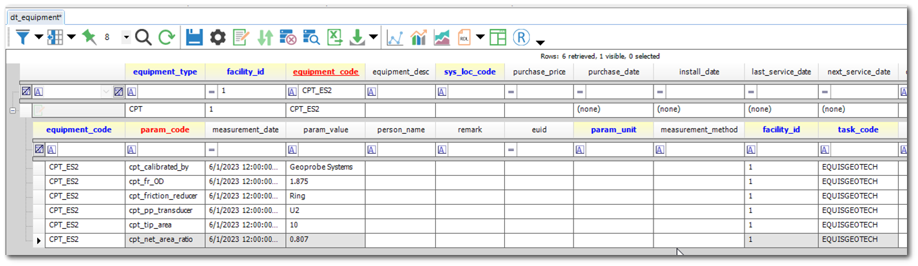
Note: The EQUIS.GEOTECH_CPT_DATA function references the Probe ID’s cpt_net_area_ratio value from the DT_EQUIPMENT_PARAMETER table. |
|---|
DT_FILE EnviroInsite and Report Graphic Configuration
Files to support graphics in EnviroInsite and reports must be uploaded the DT_FILE table and appropriate values assigned to DT_FILE.PLACE_TYPE and DT_FILE.PLACE_CODE.
There are two methods to load files to the DT_FILE table:
1.In EQuIS Professional, navigate to the Docs & Photos Form. In the Docs & Photos window, drag your DXF file(s) to the database folder. Open DT_FILE and populate the DT_FILE.PLACE_TYPE and DT_FILE.PLACE_CODE with the information outlined below.
2.In Enterprise, use the Explorer Widget to upload the graphic files. Within the Explorer Widget, the DT_FILE.PLACE_TYPE and DT_FILE.PLACE_CODE values can be defined for each file uploaded. Please follow the DT_FILE.PLACE_TYPE and DT_FILE.PLACE_CODE specificatons outlined below.
Sample Type Graphic:
•DT_FILE.PLACE_TYPE = “sample_method_graphic”
•DT_FILE.PLACE_CODE = Name of sampling method (from the RT_SAMPLE_METHOD table)
Water Observations Graphic:
•DT_FILE.PLACE_TYPE = “water_level_graphic”
•DT_FILE.PLACE_CODE = DT_WATER_TABLE.TYPE
Cave In Graphic:
•DT_FILE.PLACE_TYPE = “water_level_graphic”
•DT_FILE.PLACE_CODE = DT_WATER_TABLE.TYPE
Office Logo and Alternative Office Logo:
•DT_FILE.PLACE_TYPE = “Office Logo”
•DT_FILE.PLACE_CODE = “Default” or RT_COMPANY.COMPANY_CODE
•It is assumed that the company logo will be set to “Default”.
Note: It is suggested that Logo images uploaded to the DT_FILE table have the following dimensions: |
|---|