Using New Live File Processor Wizard (Beta)
Step 2: Name this Configuration
Editing Existing/Saved Configurations
Introduction
The new Live File Processor, included in the 25.1 Build as a Beta, facilitates configuration and data loading with a wizard-like interface that can be used in the Live File Processor Widget. The beta wizard interface walks the user through the necessary steps of identifying where in the file the logger code is found, picking series and units, identifying the date and time, and choosing the row where the data to be loaded begins in the file.
The new Live File Processor (Beta) (enabled for EarthSoft Beta users by using a feature flag) seeks to provide a much easier and quicker experience in configuring and loading data. This new functionality can:
•Setup Live File Processor configurations without the use of regular expressions (Regex).
•Establish a designated folder (i.e., folderWatcherPath) to look for data files.
•Import data immediately, without having to use the folderWatcherPath.
Notes: •Information in this article is for the Beta version of the new Live File Processor wizard. •This feature is (currently) hidden behind a feature flag. Users must enable this feature flag to use the new Live File Processor wizard (Beta). •The Live File Processor report is called by the Live File Processor wizard (Beta) when loading data (in addition to saving a configuration in the ST_CONFIG table). Therefore, the Live File Processor report must be republished to the database whenever the Live/Enterprise build is updated. |
Getting Started
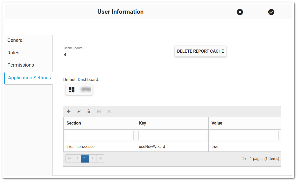
To enable the new Live File Processor wizard (Beta) feature flag:
1.In EQuIS Enterprise, click the More Options ![]() button in the upper right.
button in the upper right.
2.Select the username.
3.In the User Information window, select the Application Settings tab.
4.Click the Add ![]() button.
button.
5.Add the following information:
a.Section = live.fileprocessor
b.Key = useNewWizard
c.Value = true
6.Click the Update ![]() button.
button.
7.Click the Save changes and close ![]() button.
button.
To revert back to the Live File Processor Widget user interface, the feature flag added in the Getting Started section will need to be removed. To disable the Live File Processor (Beta) widget feature flag:
1.In Enterprise, click the More Options ![]() button in the upper right.
button in the upper right.
2.Select the username.
3.In the User Information window, select the Application Settings tab.
4.Select the Live File Processor Widget (Beta) feature flag setting.
5.Change the Value to false.
Using New Live File Processor Wizard (Beta)
The following steps require that the Live File Processor Widget be on an Enterprise dashboard (see Widget Chooser for more information).
Once the feature flag has been added, click the Add Device button to open the new Live File Processor (Beta) device configuration wizard rather than the classic Add Instance/Type dialog window. Step through the side menu options and follow the instructions to provide the information required to configure the device. As each step in the configuration wizard is completed, the side menu options will be enabled. Users can click the Back button or select a tab on the side menu to return to previous steps.
Some of the configuration steps will include a grid display of the logger file information. The width of each column in the grid display is adjustable. Users can click and drag the edge of a column in the grid header to resize that column. Users can also choose which columns to show/hide by selecting the Column Editor button at the top right of the grid. A drop-down list of check boxes for each column will open.
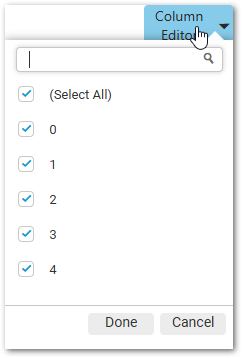
By default, all columns are checked for displaying in the grid. When a check box is disabled, that column is hidden from the grid. Choosing "(Select All)" will enable the check boxes for all columns.
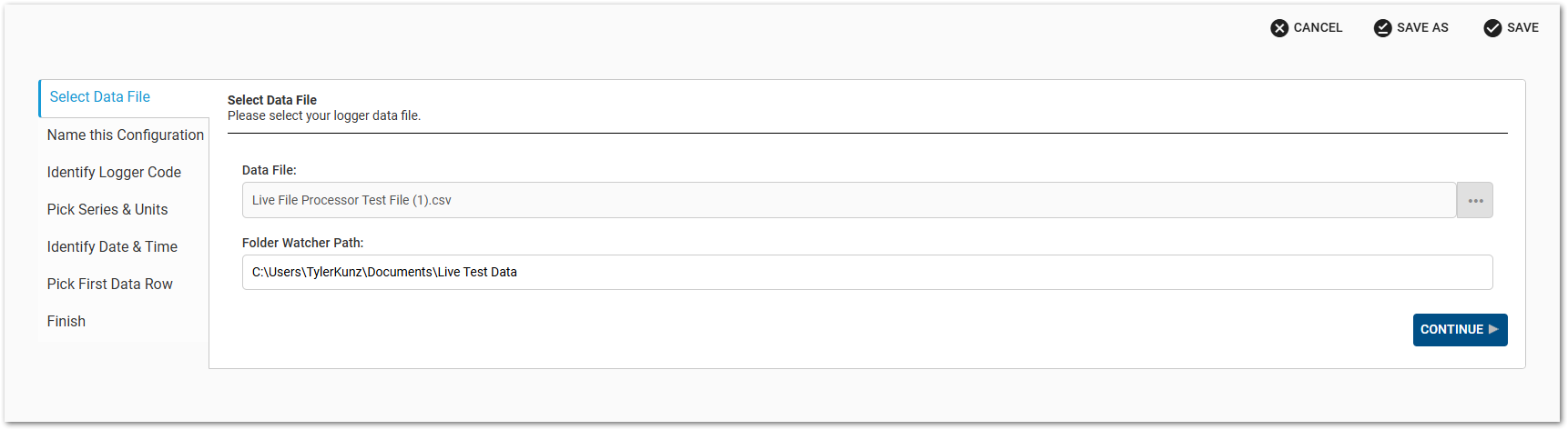
Step 1: Select Data File
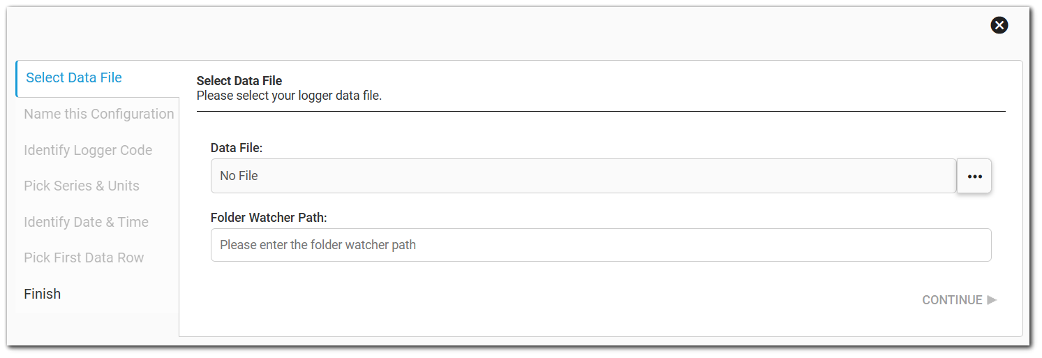
Data File – Click the Browse Files ![]() button to open the Windows file manager and select a text file (comma, tab, or pipe delimited) that contains a set of logger data. This file will be used to identify the main sections (e.g., logger name, table header for the logger data, etc.) of the data files. After the file has uploaded to the wizard, the file name will display in the text box.
button to open the Windows file manager and select a text file (comma, tab, or pipe delimited) that contains a set of logger data. This file will be used to identify the main sections (e.g., logger name, table header for the logger data, etc.) of the data files. After the file has uploaded to the wizard, the file name will display in the text box.
Folder Watcher Path – If data files will be placed in a designated folder (i.e., the Folder Watcher Path), enter the Folder Watcher Path. Multiple Folder Watcher Paths can be configured, but only one per facility. The session facility is selected by default, but can be changed. To add another facility, click the Add ![]() button, choose the facility and enter the Folder Watcher Path. To remove a Folder Watcher Path, click the Remove
button, choose the facility and enter the Folder Watcher Path. To remove a Folder Watcher Path, click the Remove ![]() button. See the Live File Processor Agent Folder article for more details.
button. See the Live File Processor Agent Folder article for more details.
Click the Continue button when done to move to the next step.
Notes: •Only *.csv and *.txt files are allowed for upload in the LFP Wizard. The selected file type (.csv or .txt) must be a valid file type in the RT_FILE_TYPE table. •The LFP Wizard currently has a limit of 120,000 rows in the data file used to setup the logger instance. •When setting the Folder Watcher Path, the user must have editor permission to the configuration facility. •The LFP Wizard does not currently support connecting to an Azure storage account or blob container. The standard Live File Processor Widget supports connection to Azure containers (see Live File Processor Agent Folder - Azure for more information). |
Step 2: Name this Configuration
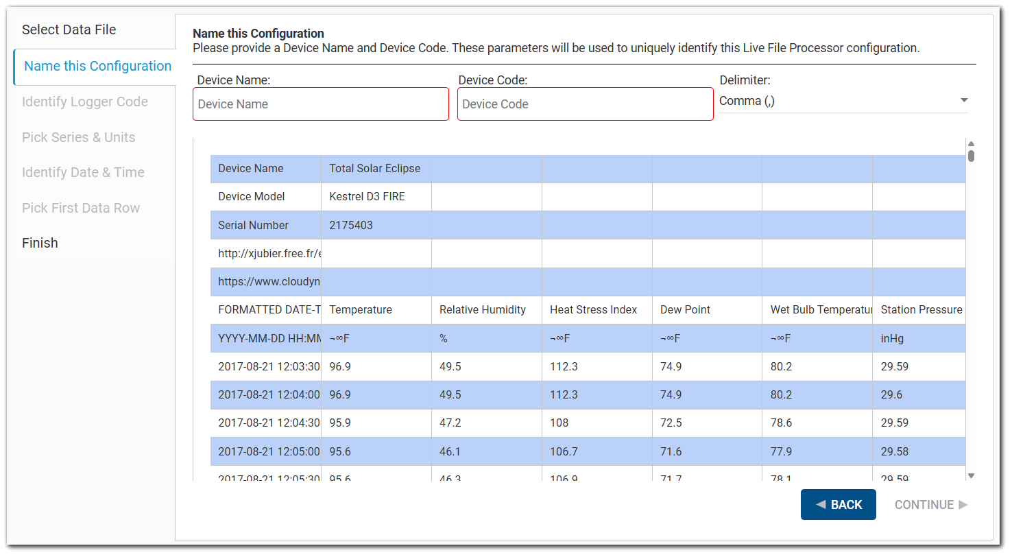
The comma, tab, or pipe delimited file selected in Step 1 will display in the wizard. The program determines which character is most likely to be the file's delimiter. The grid displays the file contents based on the identified delimiter. The Delimiter field on the right indicates which delimiter was chosen. If the program accidentally identifies the wrong delimiter, this will be evident in the data grid because the values contained in each cell will appear skewed. If this happens, select the appropriate delimiter from the drop-down and the grid will automatically adjust.
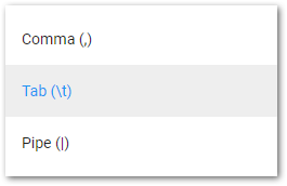
To change the Delimiter, click the Delimiter drop-down to display the Delimiter options:
After verifying the file loaded appropriately, enter a Configuration Name that will be used to identify the Live logger data configuration file. By default, the Configuration Name will populate with the name of the file loaded in Step 1 but can be changed.
Click the Continue button when done to move to the next step. If the Configuration Name already exists, the user will be prompted to either Save As a new Configuration Name or overwrite the existing file.
Step 3: Identify Logger Code
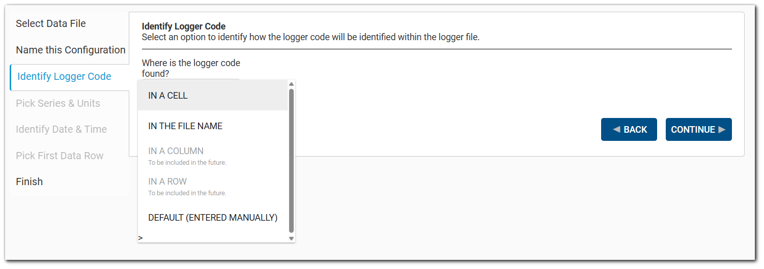
Select the drop-down and choose from the following options to determine how the logger code will be identified within the logger data file:
•In a Cell
•In the File Name
•In a Column
•In a Row
•Entered Manually (default)
In a Cell Option
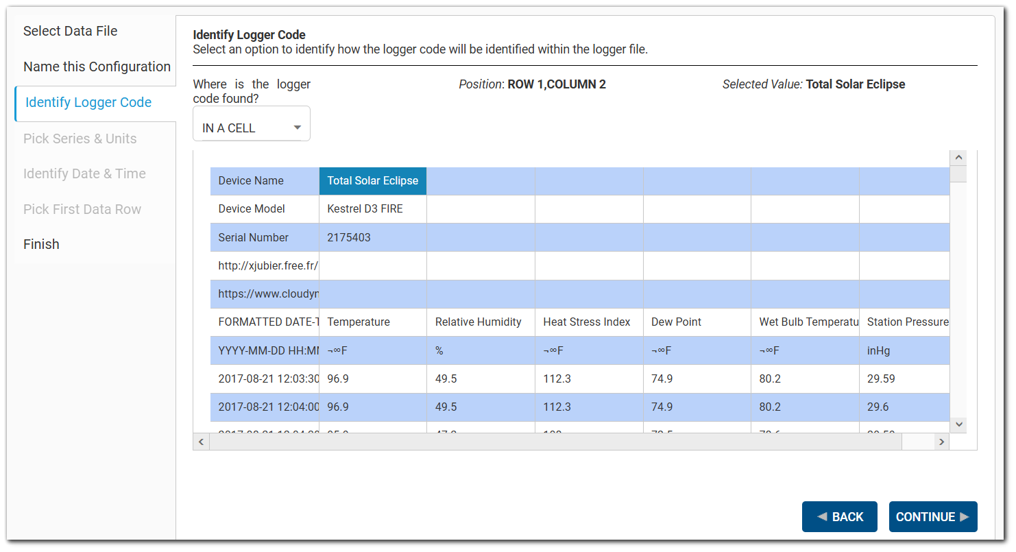
When the "In a Cell" option is chosen, two labels will appear to the right of the drop-down entitled Position and Selected Value. Click on the cell in the data grid for the logger code. The Position will give the index of the selected cell and the value will be shown in the Selected Value display box.
In the File Name Option
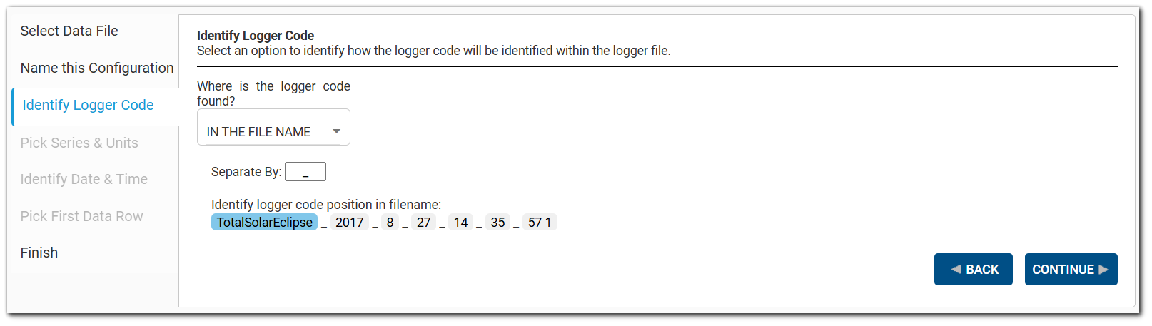
When the "In the File Name" option is chosen, the file name for the uploaded data file will be parsed by the character(s) noted in the "Separate By" box, which defaults to a period (.). Change the separator if applicable. Once the file name is appropriately parsed, select the portion that contains the logger code. The selected text will be highlighted in blue.
In a Column Option
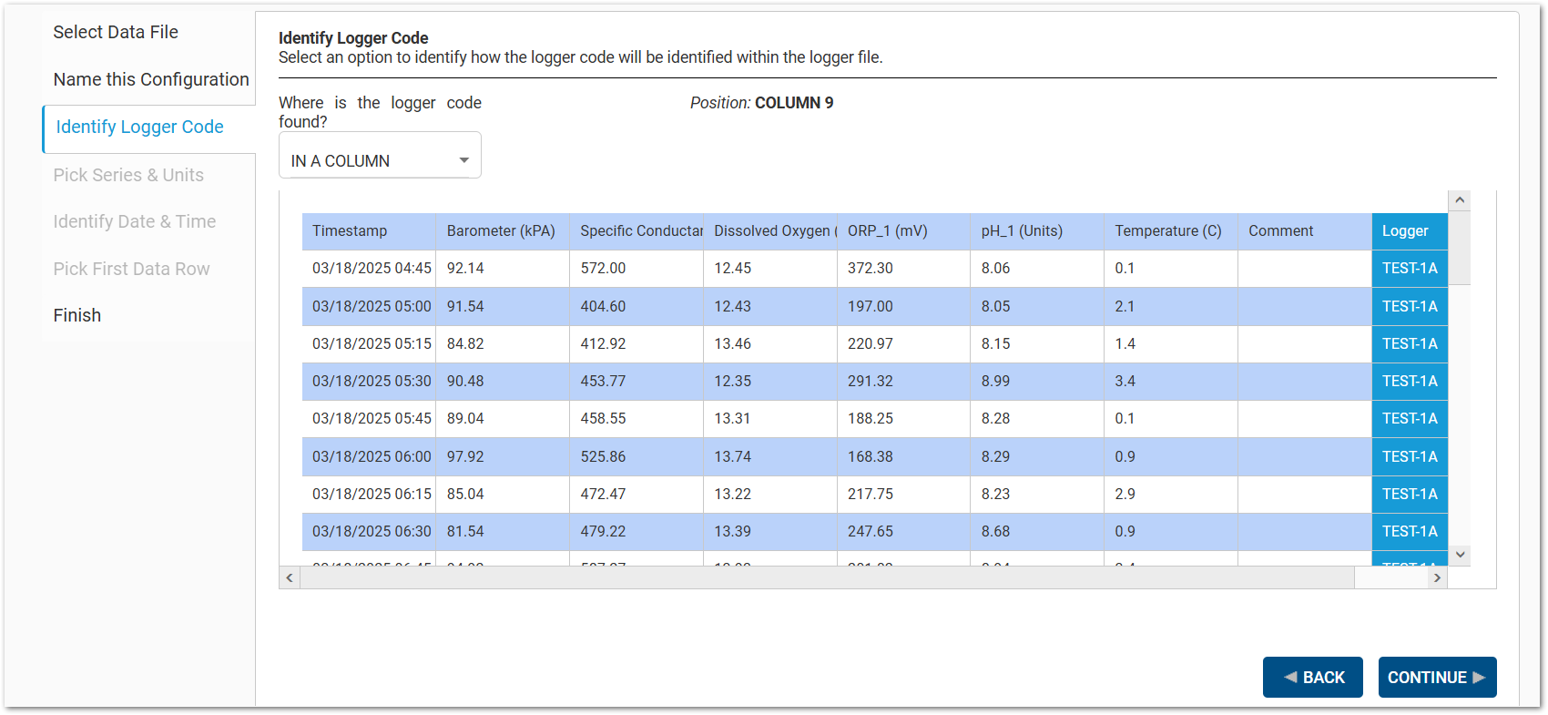
When the "In a Column" option is chosen, the uploaded data file will be parsed and each row will have its data linked to the logger in the same row. Select the column containing the logger codes (logger names). The selected column will be highlighted in blue.
Parse Type – Drop-down selection that allows users to parse a subsection of the contents of the column cell based on specific criteria.
None – When selected, no parsing happens and the full content of the cell is used for the logger code. The default Parse Type is None.
Search – When selected, users can enter a "Start After" and/or an "End Before" value. The wizard will search the cell contents for the "Start After" value and return the text after that string as the logger code. Search using the "End Before" value is similar to the "Start After", but it returns the cell text of everything before the "End Before" value as the logger code. Both options can be used in tandem to get a value between them. At least one value is required when Search is selected.
Position – When selected, users can enter a "Start" position and/or an "End" position that will be used as indexes on where the parsing should occur within the cell to define the logger code. Both must be numeric integer values. The "Start" option will use the integer value and extract the cell content after the index. The "End" option will use the integer value and extract the cell content before the index. The logger code will be extracted starting at the "Start" position and ending at the "End" position when used in tandem. At least one value is required when Position is selected. The "Start" value cannot be greater value than the "Before" value.
In a Row Option
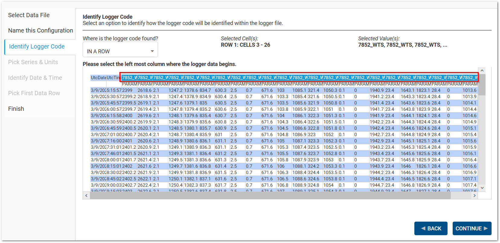
When the "In a Row" option is chosen, the uploaded data file will be parsed and each column will have its data linked to the logger in the same column. Click the left-most cell in the row where the logger data begins. The selected row cells will be highlighted in blue.
Parse Type – Drop-down selection that allows users to parse a subsection of the contents of the row cell based on specific criteria.
None – When selected, no parsing happens and the full content of the cell is used for the logger code. The default Parse Type is None.
Search – When selected, users can enter a "Start After" and/or an "End Before" value. The wizard will search the cell contents for the "Start After" value and return the text after that string as the logger code. Search using the "End Before" value is similar to the "Start After", but it returns the cell text of everything before the "End Before" value as the logger code. Both options can be used in tandem to get a value between them. At least one value is required when Search is selected.
Position – When selected, users can enter a "Start" position and/or an "End" position that will be used as indexes on where the parsing should occur within the cell to define the logger code. Both must be numeric integer values. The "Start" option will use the integer value and extract the cell content after the index. The "End" option will use the integer value and extract the cell content before the index. The logger code will be extracted starting at the "Start" position and ending at the "End" position when used in tandem. At least one value is required when Position is selected. The "Start" value cannot be greater value than the "Before" value.
Entered Manually Option
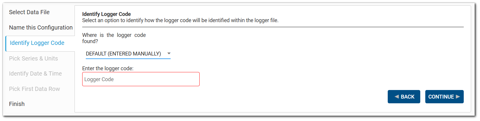
When the "Entered Manually" option is chosen, a text field is displayed to enter the logger code.
Note: This logger code will be used for any and all files loaded using this configuration. |
|---|
Click the Continue button when done to move to the next step.
Step 4: Pick Series & Units
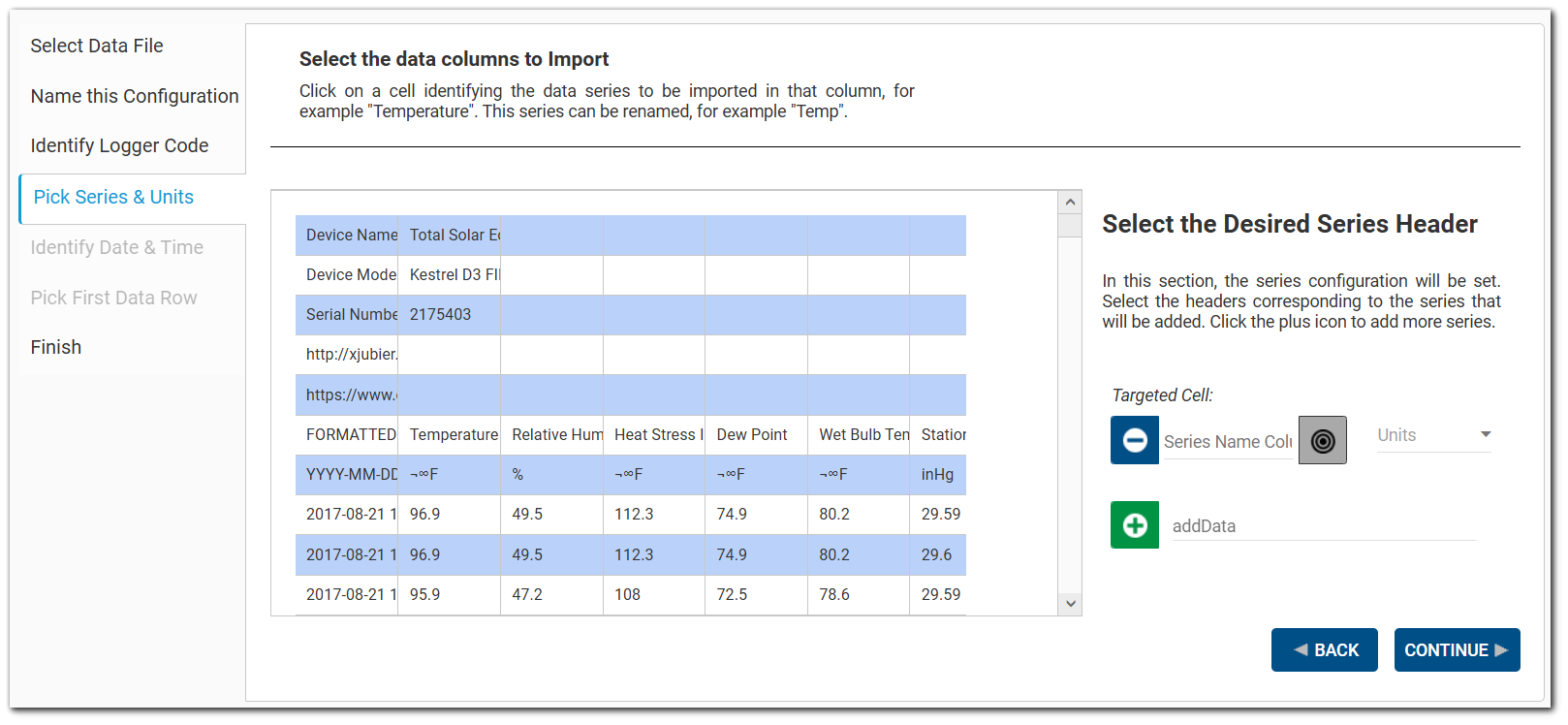
On this tab, configuration of the data series (e.g., temperature, dew point, etc.) will be set. Data series are assumed to be in discrete columns in the data grid. By default, a single data series configuration box will be displayed.
To identify a data series for import, click the Target ![]() button and then select the cell in the data grid that has the desired header value (e.g., temperature). The targeted cell within the file will display above the selection and the name of the header row will populate in the text box. The text box is editable and can be changed as desired.
button and then select the cell in the data grid that has the desired header value (e.g., temperature). The targeted cell within the file will display above the selection and the name of the header row will populate in the text box. The text box is editable and can be changed as desired.
Once the data series has been set, choose the appropriate corresponding unit for the data series from the Units drop-down. Values in the Units drop-down menu are populated from the RT_UNIT table. To help users find the correct unit from a long list, users can enter text in the filter at the top of the Units drop-down list and the drop-down list reduces to items that match the entered text.
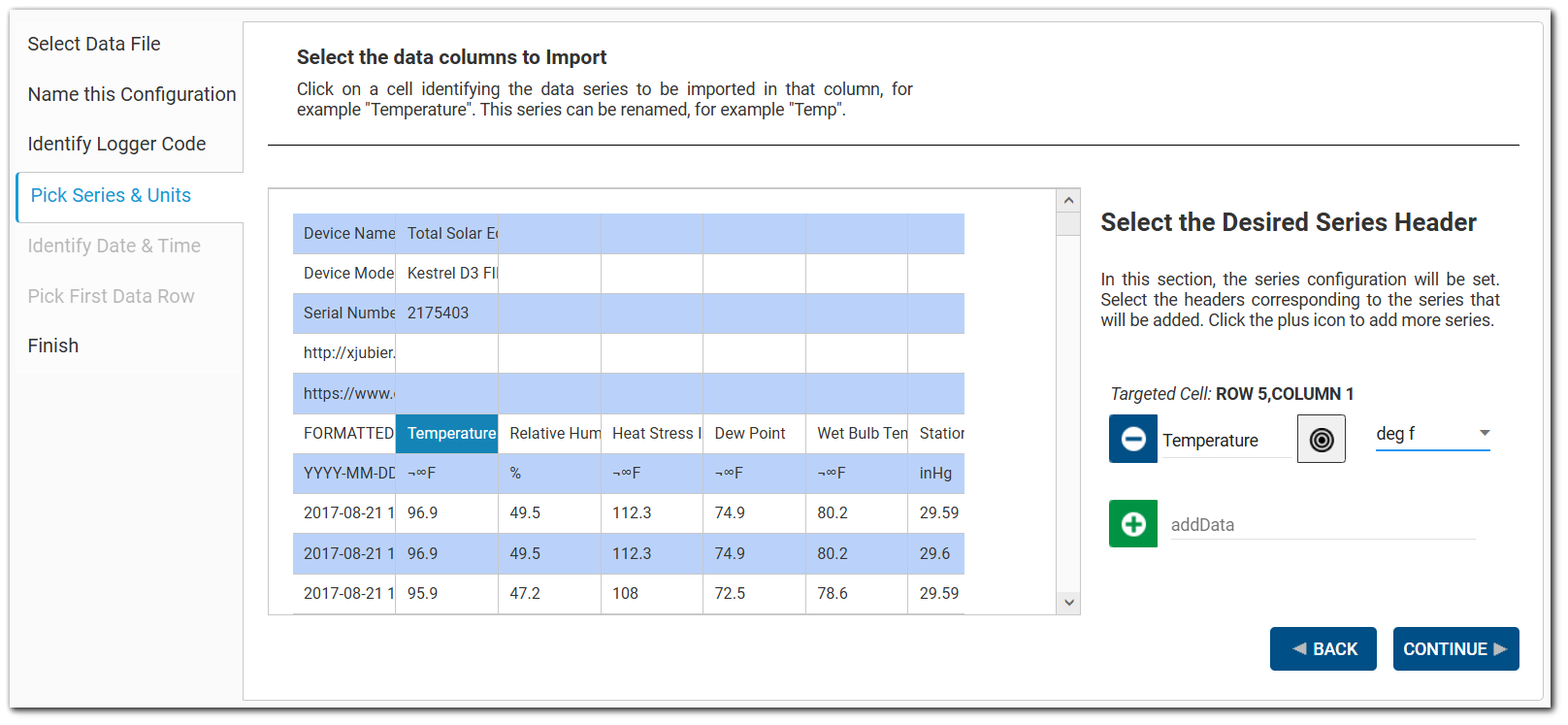
To add another data series, click the Add Data ![]() button and repeat the process.
button and repeat the process.
To remove a data series, click the Remove Data ![]() button and the series will be deleted.
button and the series will be deleted.
Note: The series will be removed without a warning message but can be added again before finishing. |
|---|
Click the Continue button when done to move to the next step.
Step 5: Identify Date & Time
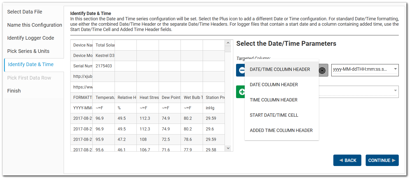
The Date and Time format and header location(s) for the device configuration is set on this tab. The following date/time parameter options are available:
•Date/Time Column Header
•Date Column Header
•Time Column Header
•Start Date/Time Cell
•Added Time Column Header
For standard Date/Time formatting, users can select either the combined Date/Time Column Header option or both the separate Date and Time Column Header options. For logger files that contain a start date and a column containing added time, users can select the Start Date/Time Cell and Added Time Column Header options.
Click the Target ![]() button and then choose the appropriate parameter option. After choosing the desired option, click on the cell in the data grid that matches the selected option. The targeted column cell will display above the parameter box. Click the Format drop-down to choose the desired date/time format.
button and then choose the appropriate parameter option. After choosing the desired option, click on the cell in the data grid that matches the selected option. The targeted column cell will display above the parameter box. Click the Format drop-down to choose the desired date/time format.
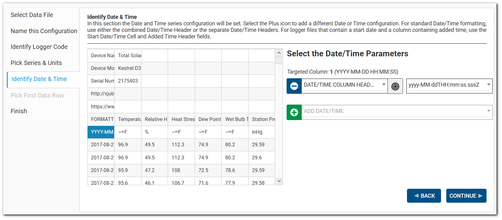
To add another date/time option, click the Add Date/Time ![]() button and repeat the process.
button and repeat the process.
Notes: •If the selected parameter is a Date/Time Column Header and the user changes the parameter to the Date Column Header, the wizard will automatically create two parameters: a Date Column Header parameter and a Time Column Header parameter. •If the user selects a Start Date/Time Cell parameter, the wizard will attempt to add an associated Added Time Column Header parameter. |
|---|
To remove a data series, click the Remove Data ![]() button and the series will be deleted.
button and the series will be deleted.
Click the Continue button when done to move to the next step.
Step 6: Pick First Data Row
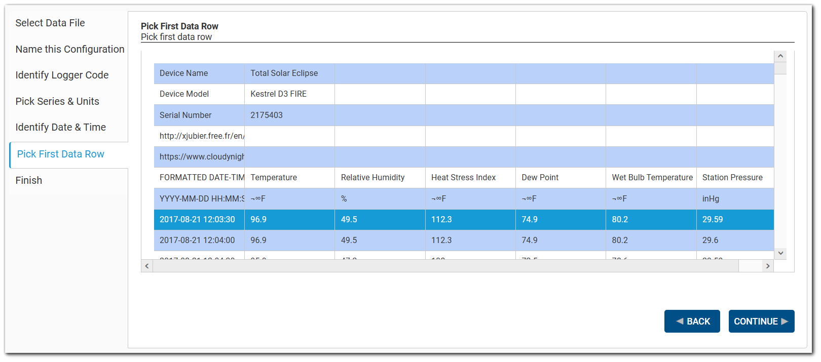
In this tab, select a single, complete row that will be used in the configuration to indicate where in the data file to start loading data. The row will be highlighted.
Click the Continue button when done to move to the next step.
Step 7: Finish
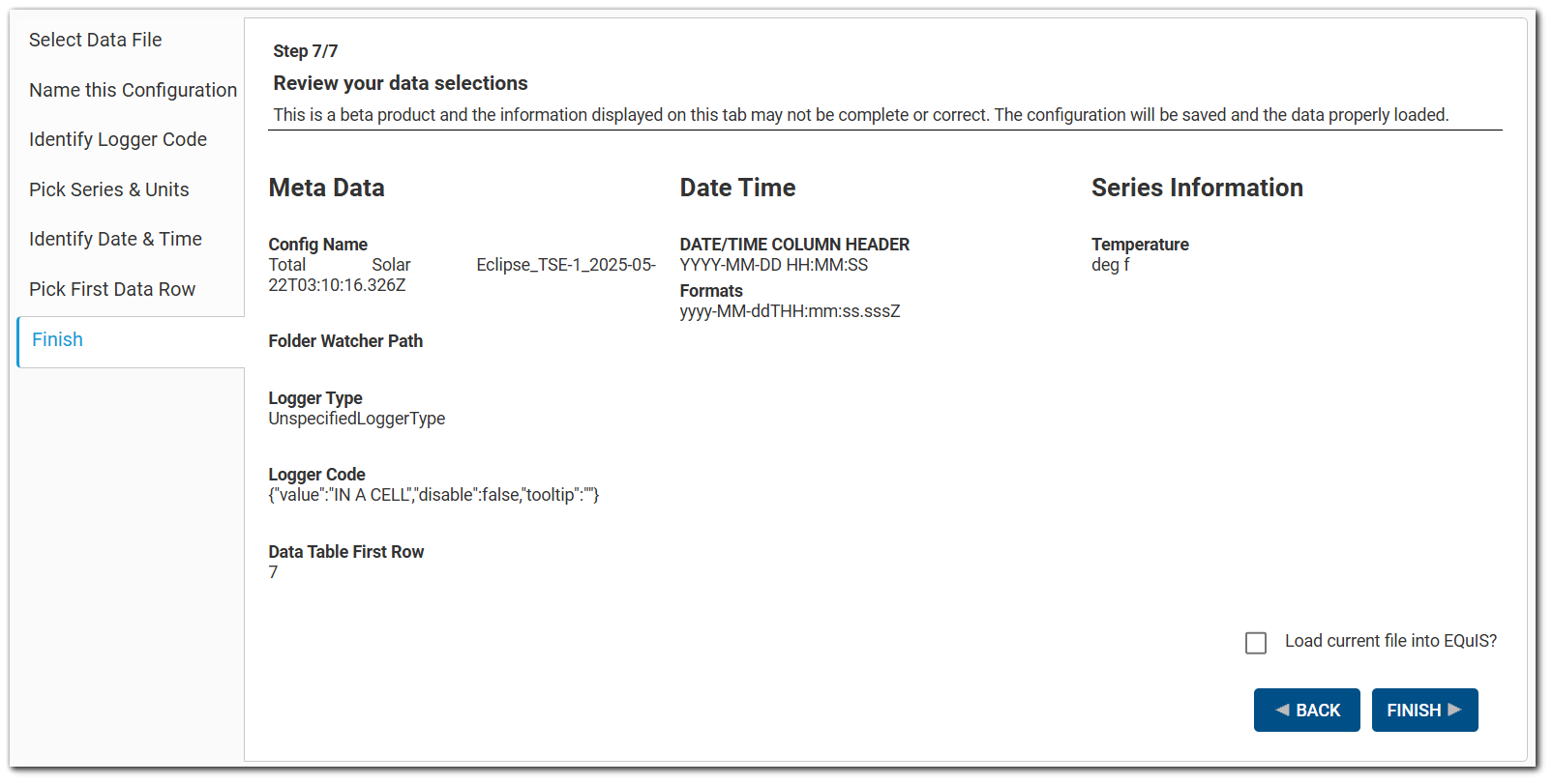
Click the Finish button to save the configuration. This configuration will be available in the ST_CONFIG table when importing logger data into EQuIS Live.
To load the current file into EQuIS in addition to creating the configuration, click the Load current file into EQuIS? checkbox. The Finish button will change to "Finish and Load". Click the Finish and Load button. After the data file is loaded, a pop up shows the result of the load and if it was successful or if there were any errors.
Note: For the file upload to be successful, .csv must be a valid FILE_TYPE in the RT_FILE_TYPE table. |
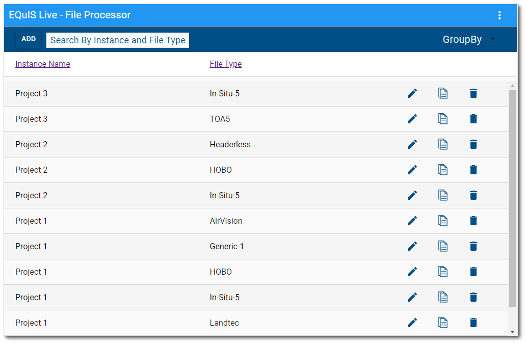
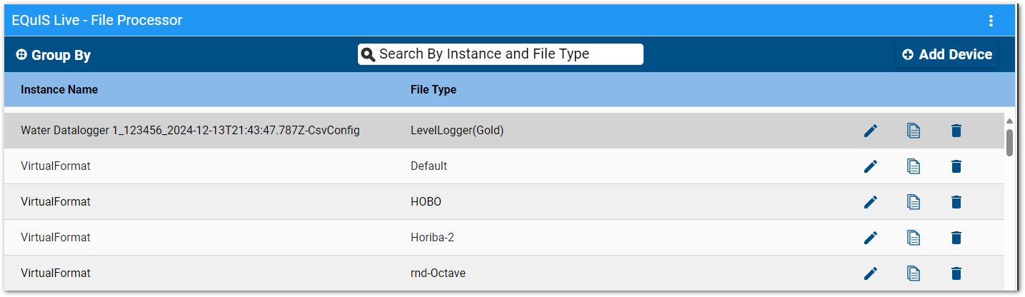
After clicking the Finish button, the new Live File Processor (Beta) configuration wizard will close. In the Live File Processor widget, the newly created configuration will be listed with a name composed of the Device Name and Device Code. The template name will have "-CsvConfig" appended to it.
Using the Configuration
Once files are added to the folder indicated in the Folder Watcher path, they can be loaded into EQuIS Professional via the EQuIS Live File: Processor report.
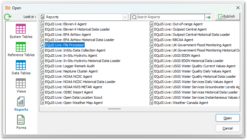
1.In EQuIS Professional, open the EQuIS Live File: Processor report.
2.For File types, select a Live File Processor Widget (Beta) configuration template file.
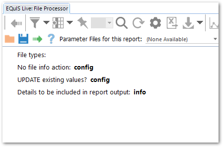
3.Click the Go ![]() button to run the report.
button to run the report.
4.A message will indicates that the data were processed.
Editing Existing/Saved Configurations
Clicking the Edit button ![]() next to an existing or saved configuration will open a new Editor window.
next to an existing or saved configuration will open a new Editor window.
To create a new configuration based on the current configuration, click SAVE AS which will open the Save a New Template window.
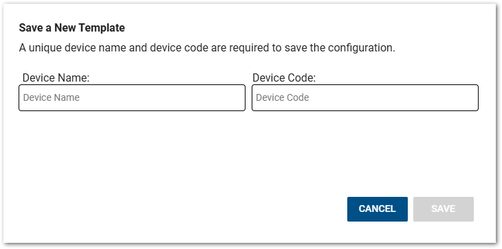
Enter a unique Device Name and Device Code and click SAVE to create the new configuration.
Note: The Live File Processor Wizard (Beta) Editor window will open if the Live File Processor Instance Name ends with "-CsvConfig", which is automatically appended to each Live File Processor Wizard (Beta) file name. |