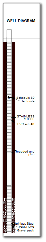
The well construction diagram includes both the fill material used in construction of the well and the essential hardware, such as the casing, screen, surface casing, cap, etc. The hatch patterns used in representation of the fill material are selected from the Fill Style tab. Well construction diagrams may be drawn either to scale (so that the hole and infrastructure radii are of the same relative scale) or in a simpler representation that simply fills the allotted space.
Note: Font styles used in the well construction logs are defined as document properties and set in the Text Style window. |
Nested Wells
For non-EQuIS database users, nested wells may be displayed by placing a comma-delimited list of location IDs for co-located wells in the Colocated field of the Locations table.
The Well Construction log will display based on what is set in the EQuIS Setup form. If it is not displaying as expected, check the EQuIS Setup form.
The Well Construction tab of the EQuIS Setup form determines what values from DT_WELL_SEGMENT or DT_GEO_BACKFILL display as the backfill and what shows as the hardware of the well construction.
The slotted lines in the middle of the diagram are the screen section of the well. The segment type that is considered the screen is set on the Sample Interval Horizon tab of the EQuIS Setup form under the "dt_well_segment.segment_type values referring to a sample interval". The SEGMENT_TYPE used as a screen must also be included in the "Well Interval segment_type Values" of the Well Construction tab.
Multiple screens or nested wells may be drawn by populating the DT_LOCATION.PARENT_LOC_CODE field for each of the nested wells. Multi-screen wells, where the screens are drawn aligned vertically, are indicated by not including a casing record in DT_WELL_SEGMENT for the locations representing the individual screens. Multiple generations may be used to draw a multi-screen well as the second of multiple nested wells. See the Multi-Screen Wells article for more information.
Creating Well Construction Profile
Double-click on the well construction field to add it to the report. Once in the report, double-click the well construction object to open the Well Construction dialog box. Modify the Options tab, Fill Style tab, Format tab, and Diameter tab as desired. Click the OK button to save changes.
Check the Show Text Description box (below) to have descriptions of individual well elements appear on the boring log. For EQuIS users, the text description will be applied based on text rotation.
•If Text Rotation (on the Format tab) is set to 'Vertical', DT_WELL_SEGMENT.MATERIAL_TYPE_CODE will be used. Only text associated with fields set in the 'Back Fill' on the Well Construction tab of the EQuIS Setup form will be displayed.
•If Text Rotation is set to 'Horizontal', the first non-null value of the following fields will be used:
•DT_WELL_SEGMENT.REMARK,
•RT_WELL_SEGMENT_TYPE.MATERIAL_TYPE_DESC, or
•DT_WELL_SEGMENT.MATERIAL_TYPE_CODE.
•Materials from the DT_GEO_BACKFILL table will use the field DT_GEO_BACKFILL.MATERIAL_NAME for both the 'Vertical' and 'Horizontal' Text Rotation settings. The DT_GEO_BACKFILL option is only applicable when the Geotech Schema is applied to the database.
Non-EQuIS users should place the text description values in the Notes field.
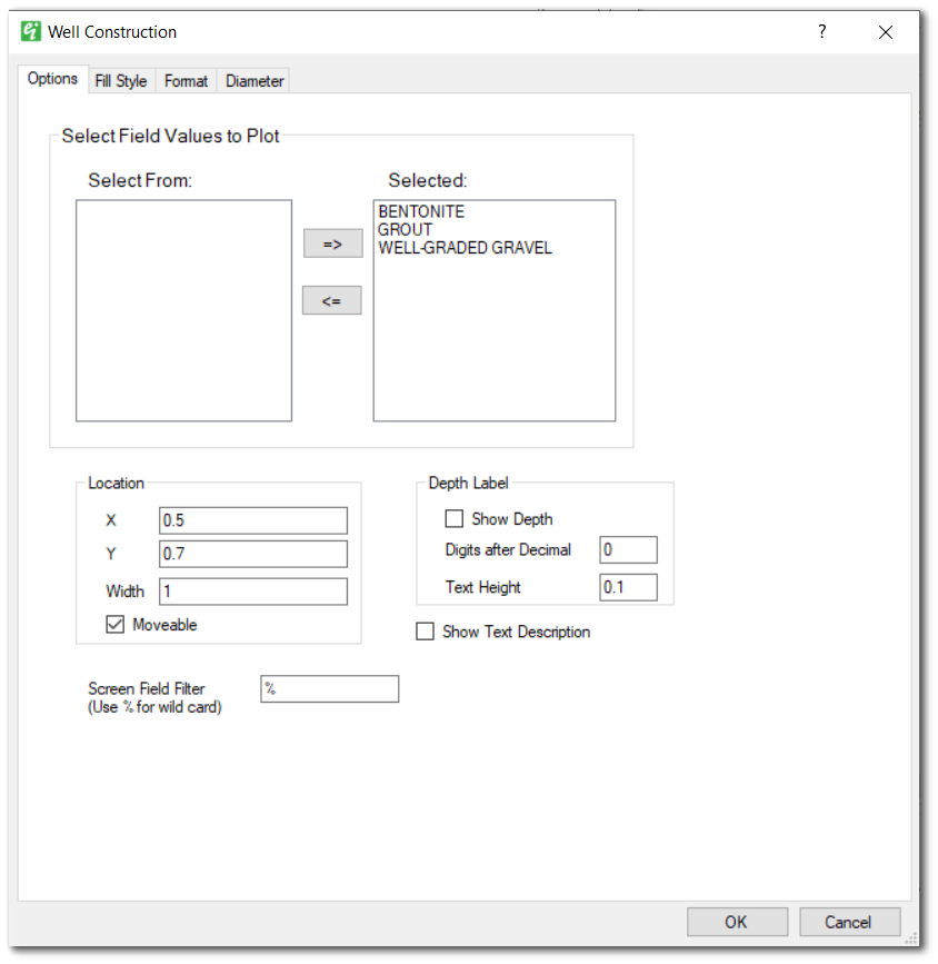
Select Field Values to Plot – List of fill material IDs that may be drawn in resulting well construction diagram. Click the => button to add or the <= button to remove item from the Selected list of fill materials to be drawn. Only fill materials from the Selected list may be edited in the Fill Style tab.
Location X and Y – Enter page location (in inches) of upper-left corner of well construction diagram.
Location Width – Enter width (in inches) of well construction diagram.
Location Moveable – Check to allow diagram to be moved using cursor/mouse.
Depth Label - Show Depth – Check to print depth on well construction diagram.
Depth Label - Digits after Decimal – Enter number of digits after decimal for printed depth values.
Depth Label - Text Height – Enter height (in inches) of printed depth values.
Show Text Description – Check to show descriptions of individual elements (source described above).
Screen Field Filter (Use % for wild card) – Enter Screen values to be used for representation of well screens, where "%" is wildcard character(s).
Hatch patterns will only be displayed when 'Specify Diameter' or 'Default' are chosen on the Diameter tab.
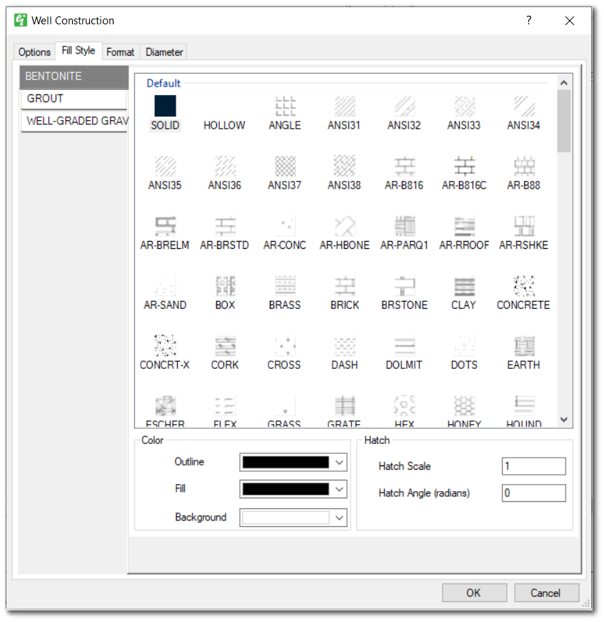
Fill Name – Select a fill material in the left side pane, from which the hatch style is to be selected.
Hatch Style – Select the hatch style for the selected fill material.
Color Outline – Select the color of the rectangular outline.
Color Hatch Lines – Select the hatch-line color.
Color Background – Select the background color. The background color can be set to transparent to allow columns below the hatch pattern to be visible.
Hatch Scale – Specify the hatch scale (increase if only the hatch line color is visible as solid object).
Hatch Angle (radians) – Set the hatch angle to rotate the hatch pattern.
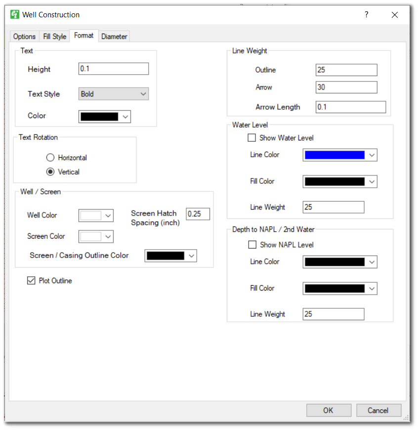
Text – Specify the text format parameters.
Text Rotation – Select the appropriate button to place the descriptive element text rotated so that it goes from the bottom towards the top of the page (Vertical) or from left to right (Horizontal).
Well/Screen - Well Color – Select the casing background color.
Well/Screen - Screen Color – Select the screen background color.
Well/Screen - Screen/Casing Outline Color – Select the screen and casting outline colors.
Well/Screen - Screen Hatch Spacing – Enter the vertical distance (in inches) between the horizontal lines used to represent the screen interval.
Plot Outline – Check to draw outline around the well construction diagram.
Line Weight Outline – Specify the outline weight (in 100ths of mm).
Line Weight Arrow – Specify the arrow line weight (in 100ths of mm).
Line Weight Arrow Length – Specify the arrow length (in inches).
Show Water Level – Check to show water level within the well construction element.
Water Level – Specify the outline and fill color and line weight of the inverted triangle representing either the water table or NAPL elevation.
Depth to NAPL/2nd Water - Show NAPL Level – Check to show the secondary water level or NAPL level.
Depth to NAPL/2nd Water – Specify the outline and fill color and line weight of the inverted triangle representing either the secondary water table or NAPL elevation.
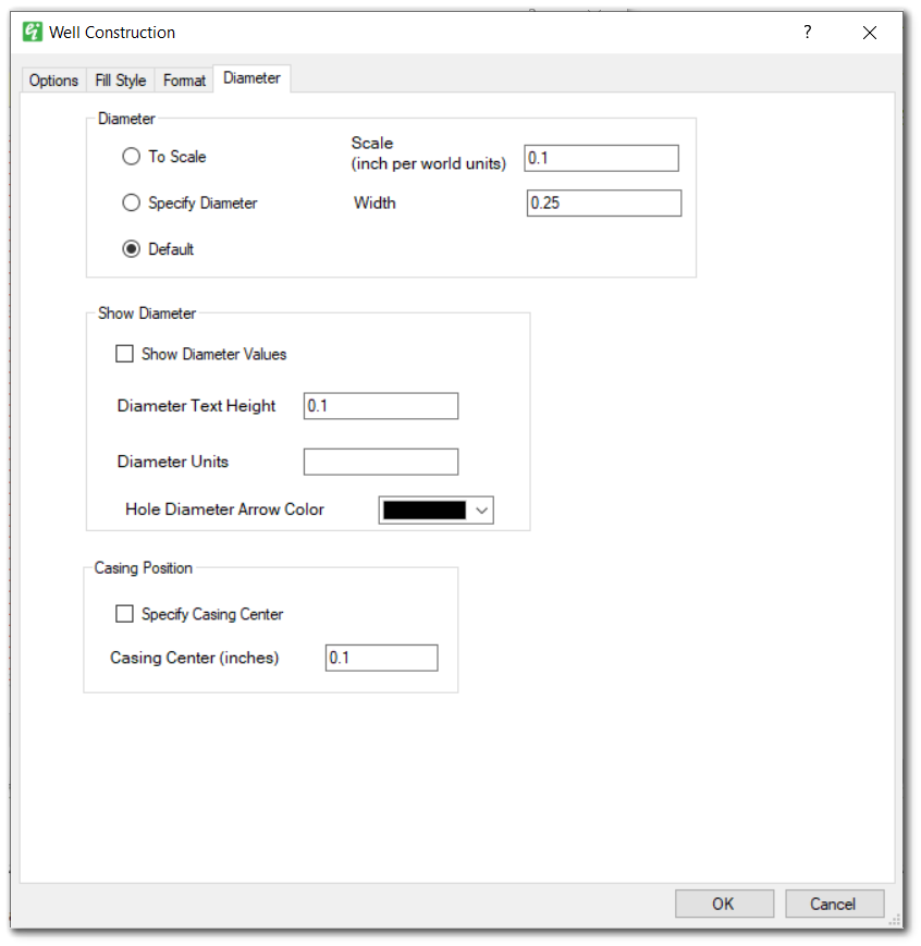
Diameter – Select the appropriate button to plot well-construction radii to scale, to specify the borehole diameter (in inches), or to allow the program to select a default value.
Note: Hatch styles will only be displayed when 'Specify Diameter' or 'Default' are chosen for the borehole diameter. |
Diameter Scale (inch per world units) – Set the diameter scale (only used if 'To Scale' is selected).
Diameter Width – Set the borehole width (in inches; only used if 'Specify Diameter' is selected).
Show Diameter Values – Check to show the element diameter values on the well construction diagram.
Show Diameter – Set the diameter text height and display units.
Casing Position - Specify Casing Center – Check to indicate the casing center (otherwise calculated by program).
Casing Position - Casing Center (inches) – Indicate the casing horizontal center in inches relative to the left edge of the well construction diagram.