•Multi-Screen and Nested Wells in Single Borehole
The EQuIS Database Schema is capable of representing both multi-screen and nested wells. The multi-screen configuration represents a single casing equipped with multiple screens or multiple sample devices used to determine local conditions at various intervals. It also includes the installation of multiple transducers for measurement of potentiometric head at discrete intervals, where there is no capability of obtaining water samples. The nested well configuration also allows for the collection of water samples or measuring of potentiometric head at discrete intervals from a single borehole, however, multiple casings or lines are installed within the borehole. The multiple casings and screens or sampling devices are referred to as a set of nested wells or devices.
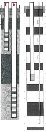
The figure at right shows two boreholes. The borehole on the left shows two nested wells installed within a single borehole. The screened intervals are separated by bentonite seals to ensure that the intervals are hydraulically isolated. In the right-side of the figure, the borehole is equipped with both a single monitoring well of moderate depth and multiple transducers (represented by the hollow rectangular shapes) at multiple depths. This is essentially a hybrid of the nested well and multi-screen wells within a single borehole.
Through EQuIS Version 6.6, records within DT_WELL_SEGMENT are representative of either sampling devices or well screens and are identified as such, based on the content of DT_WELL_SEGMENT.SEGMENT_TYPE. Typically, English speaking users will elect to use SCREEN as the DT_WELL_SEGMENT.SEGMENT_TYPE value that indicates that the DT_WELL_SEGMENT record is representative of a well screen. Non-English speaking users may opt to use a local translation, and some users may desire the selection of multiple SEGMENT_TYPE values to identify DT_WELL_SEGMENT records that describe either well screens or other types of sampling devices. EQuIS reports that identify the depth or elevation of individual multi-screen devices will rely on report parameters that allow users to specify the SEGMENT_TYPE values that indicate that a DT_WELL_SEGMENT record refers to a well screen or sampling device. In EnviroInsite, the SEGMENT_TYPE values associated with sampling devices and well screens are designated using application level parameters.
In EQuIS 7 and later, DT_WELL_SEGMENT values that reference either screens or sampling intervals will be identified based on the contents of the SEGMENT_TYPE and MATERIAL_TYPE codes, and the value of IS_SCREEN_YN in the associated record in the RT_WELL_SEGMENT table. If the value of RT_WELL_SEGMENT.IS_SCREEN_YN is Y for records in DT_WELL_SEGMENT with common SEGMENT_TYPE and MATERIAL_TYPE_CODE values, then this record within DT_WELL_SEGMENT will be considered as a sampling interval or well screen.
Representation of multi-screen and nested wells relies on the designation of parent SYS_LOC_CODE values in the DT_LOCATION.PARENT_LOC_CODE field. In general, the individual nested wells would have PARENT_LOC_CODE field values that point to the borehole. In that sense, the nested wells may be referred to as being of second generation relative to the first-generation borehole.
The representation of several specific conditions is described below. These are (1) a single multi-screen well or single well with multiple sampling or other measurement devices, (2) a set of nested wells or devices within a single borehole, and (3) one or more single-screen and multi-screen wells within a single borehole.
In the case of a single multi-screen well, the SYS_LOC_CODE associated with the borehole serves as the parent SYS_LOC_CODE for the DT_LOCATION records associated with each of the individual screens or sampling devices.
In the DT_WELL_SEGMENT table, the backfill materials and the casing intervals are designated using the SYS_LOC_CODE of the parent borehole. Individual records within DT_WELL_SEGMENT are also used to represent the start and end depth of the multiple individual screens. Including a record within DT_WELL_SEGMENT for representation of the screens or sampling intervals also requires the addition of records with the same SYS_LOC_CODE in DT_LOCATION and DT_WELL. One of the benefits of this method of representing multi-screen wells is that each sampling point has a unique SYS_LOC_CODE that can be referenced as a sampling interval in DT_SAMPLE or DT_WATER_LEVEL.
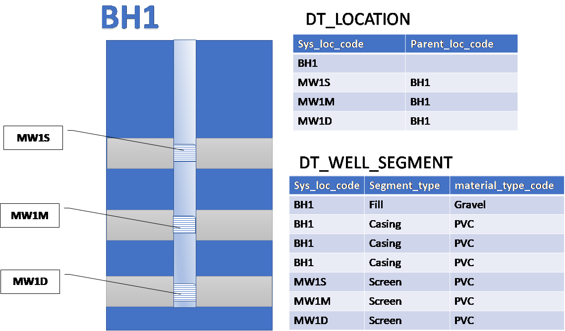
The figure below contains an example of a single multi-screen well. In this case, BH1 is the parent location and all of the associated fill, gravel, and seal records in DT_WELL_SEGMENT will be associated with the BH1 SYS_LOC_CODE value. Likewise, the casing records in DT_WELL_SEGMENT will carry a SYS_LOC_CODE value of BH1. The well screens are represented with DT_WELL_SEGMENT records and carry the SYS_LOC_CODE associated with each screen (i.e., MW1S, MW1M, and MW1D). These locations are progeny of BH1, and as a result, would be represented in DT_LOCATION with PARENT_LOC_CODE values of BH1.
As in the previously described case of the single multi-screen well, DT_WELL_SEGMENT records describing backfill will use SYS_LOC_CODE values that refer to the parent borehole. Likewise, each of the individual screens or sampling points are described in records with unique SYS_LOC_CODES within DT_WELL_SEGMENT. In addition, within DT_LOCATION, the PARENT_LOC_CODE field of each of the daughter wells is populated with the SYS_LOC_CODE value of the parent borehole. The main difference between the multiple nested wells case and the single multi-screen well case is that the records in DT_WELL_SEGMENT that refer to the casing and other well infrastructure of the individual wells will be populated with the well’s second-generation SYS_LOC_CODE values.
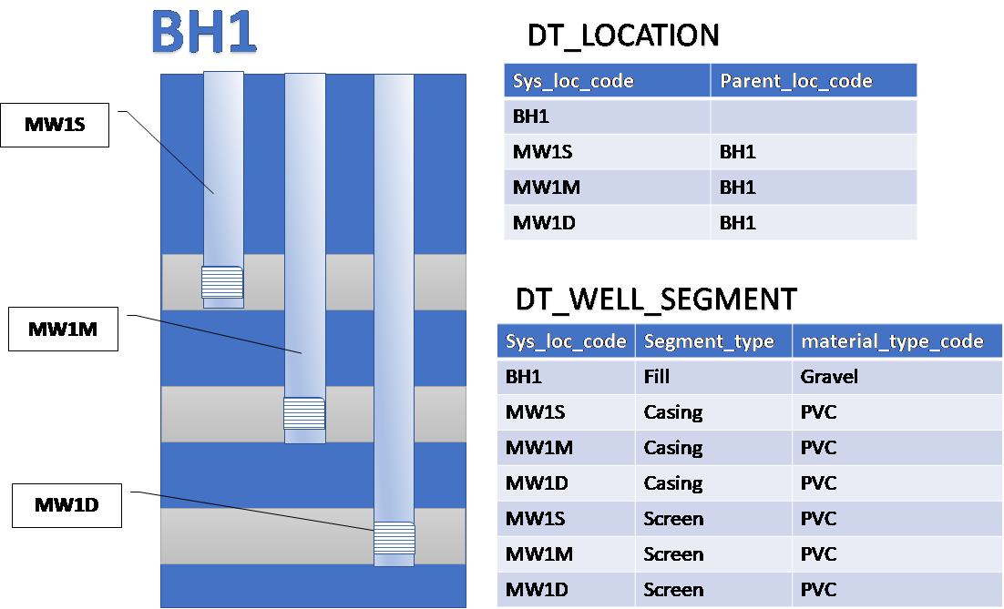
In the example below, BH1 is the parent location. As in the case of the single multi-screen well, all records referring to backfill material in DT_WELL_SEGMENT should reference the BH1 SYS_LOC_CODE value. The progeny are the single-screen wells MW1S, MW1M, and MW1D. Records for these wells in DT_LOCATION will carry PARENT_LOC_CODE values of BH1. All casing and screen records in DT_WELL_SEGMENT will carry the SYS_CODE_VALUES of the progeny wells (MW1S, MW1M, or MW1D).
Multi-Screen and Nested Wells in Single Borehole
This is a more complicated and less common configuration. An example is one or more monitoring wells installed in a single borehole (each with its own casing) and a set of transducers installed within a common line for measurement of potentiometric head at discrete depths. The use of the PARENT_LOC_CODE in this case is similar to multi-screen and nested wells, however, three generations are designated for complete representation of all infrastructure so as to assure a unique SYS_LOC_CODE associated with each sampling interval. Each of the monitoring wells and each multi-screen device will have a unique associated SYS_LOC_CODE. For each of these second-generation elements, the PARENT_LOC_CODE value in DT_LOCATION will be the SYS_LOC_CODE of the common borehole. The individual sampling devices or screens of the multi-screen well or device will be represented with unique records in DT_LOCATION and DT_WELL_SEGMENT. The PARENT_LOC_CODE values in each of their DT_LOCATION records will be populated by the SYS_LOC_CODE of the multi-screen well. These sampling intervals or well screens are in essence the third generation offspring relative to their common borehole.
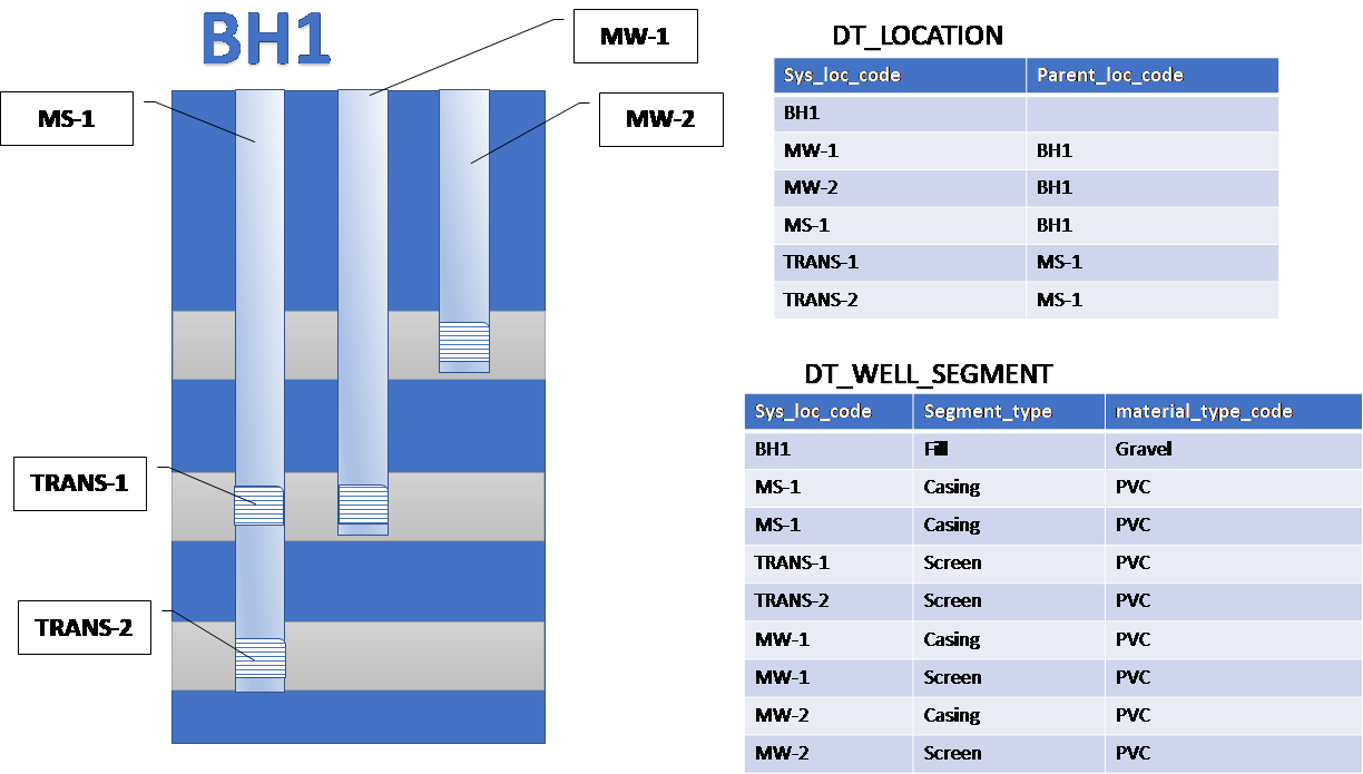
In the example below, BH1 refers to the parent borehole. All records in DT_WELL_SEGMENT that reference backfill material should carry SYS_LOC_CODE values of BH1. Each of the nested wells and the single multi-sampler device are considered to be progeny of BH1 and will have PARENT_LOC_CODE values of BH1 in their DT_LOCATION table records. The sampling points of the individual transducers will be representing with their own unique SYS_LOC_CODE values (e.g., TRANS-1, TRANS-2) and the DT_LOCATION.PARENT_LOC_CODE fields for record with these SYS_LOC_CODE values will refer to the multi-sampler device MS-1. Casing records in DT_WELL_SEGMENT for the nested wells will have the nested well SYS_LOC_CODE values (i.e., MW-1 and MW-2). The casing records in DT_WELL segment for the multi-sampler device will all have SYS_LOC_CODE values of that device (MS-1).
The Multi wells EQEDD.xls file is an example EDD and includes location, well and well segment data. This example file can assist the user to create the multi-well segments described in this article. The file is located in the EarthSoft Community Center Downloads Dashboard in the All Items> Examples > EDDs folder.