Several data loggers support real-time data streaming in EDGE, which may be imported directly into the Field Results section. Currently, the following loggers are supported:
•Horiba U-50 Series (U-51, U-52, U-52G, U-53, U-53G)
•Hydrolab (DS5X, DS5, MS5, HL4, HL7)
•YSI (EXO1, EXO2)
The sections below detail the import protocol in EDGE.
Plugin or Pair the Probe
If the probe has a serial or USB connector, plug it into the same device operating EDGE. If the probe supports Bluetooth, pair it to the device, see Connect a Bluetooth device in Windows 10 for more information.
Connect the probe to EDGE
The example below details the steps for In-Situ Modbus, the process is the same for the other probes.
1.Click Devices tab in EDGE, then the probe manufacturer; In-Situ.
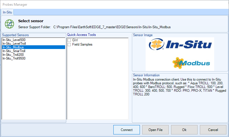
2.In the Probes Manager, click In-Situ Modbus (or other supported probe), then Connect. If a device supports this feature, the Connect button will be visible.
Note: To add a shortcut to the direct connection option in the Field Sample Form, check the appropriate form in the Probes Manager Quick Access Tools and click OK. Clicking any other button in the Probes Manager will not add the shortcut.
|
3.In the new window, obverse the Log until "A probe found" appears. If the message "No ports found" appears, check the logger connection to the device, and if possible, a connection to the vendor's software (e.g., In-Situ's Win-Situ 5).
Note: EDGE searches search for In-Situ probes on all COM ports, using a few common baud rates, modes, and device addresses, which are defined in the appSettings, in the EDGE\Sensors\In-Situ\In-Situ_Modbus\*.config file. |
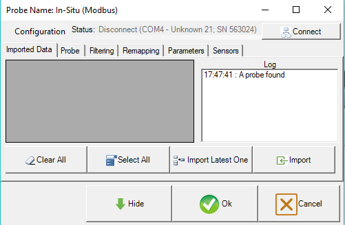
4.If a probe is found, the Status bar will show the COM port, model, and serial number (e.g., COMx - Aqua TROLL® 600 Vented; SN 416077). Click Connect to start receiving data.
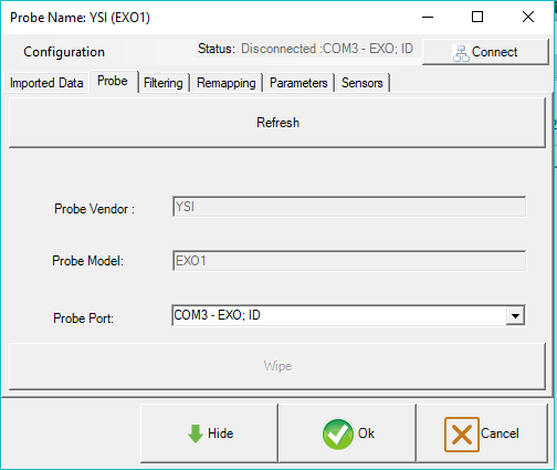
Note: If a probe is connected to more than one port, (e.g. via Bluetooth or USB), use the Probe tab to choose the appropriate port in the Probe Port dropdown.
|
Import Field Data
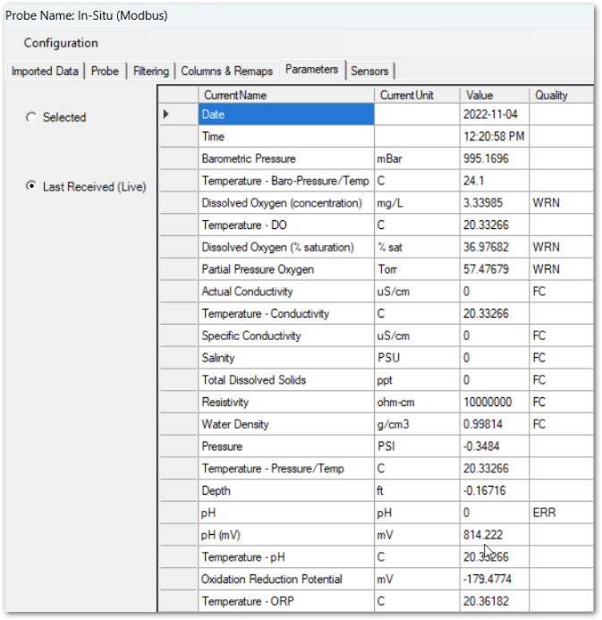
Note: Some previous setup is required. Parameters and units used by the logger, or or remapping tables, must exist in the Reference Value File (RVF) exported from the database. In the connection window, click the Parameters tab to view the parameters used by the logger. See Create Groups for Field Results, and Field Logger Import > Remapping for more setup information.
Some probes have a list of possible parameter and unit names in the EDGE\Sensors folder (e.g., EDGE\Sensors\In-Situ\In-Situ_Modbus\In-Situ_Modbus-parameters.txt and In-Situ_Modbus-units.txt.) In-Situ loggers connected to power packs will display parameter and associated sensor information as shown in the "CurrentName" column in the image below. The sensor parameter labels will be abbreviated (e.g., Temperature (C) - DO is the temperature value captured by the 'DO' sensor) if there are multiple(s) of the same parameter from different sensors.
|
1.Ensure that a sample record exists with all required fields populated in the Field Sample Tab (or Field Sample Form).
2.In the Field Sample Tab, select the desired record.
a.If the probe window has already been opened, click Hide and navigate to the Field Sample Tab, select the sample, then proceed to Step 3.
3.Navigate back to the Devices tab and reopen the logger connection window.
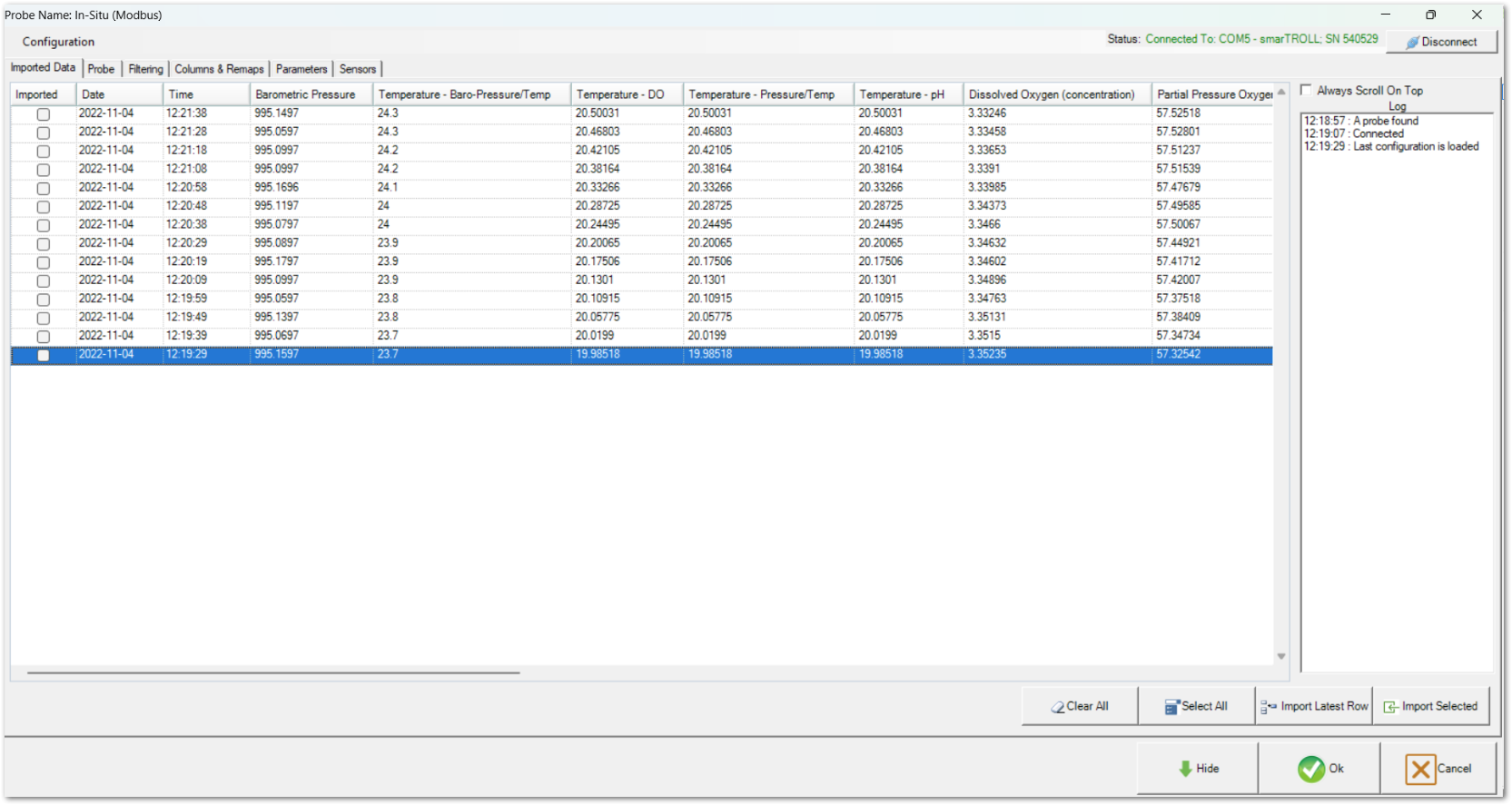
4.Click the Imported Data tab.
5.Either select a specific record and click Import, or click Import Latest One to import a record to Field Results.
a.Once a record has been imported, a check mark will appear in the Imported column for that row. Users can uncheck this box to mark as "not imported", but cannot check the box without clicking the Import button.
6.Click Hide or the minimize button in the logger connection window, and navigate to the Field Sample Tab. Check the Field Results section for new parameter values.
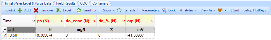
Note: Field Result rows with SENSOR_REMAP_ERRORs will not be displayed or imported by EDP. |
7.Import the EDD file into the database, using EDP; open the EDGE format and the EDD file, and Create and Commit, as described in Importing Logger Data to the Database. It will import the Parameter Values into DT_RESULT. (Importing data into the DT_LOGGER tables is not supported at this time for Live Connect.)