AutoCAD compatible DWG and DXF files (2007 and prior) can be imported to generate basemap components. CAD files commonly contain combinations of graphic primitive types such as points, polygons and lines.
To insert either a DXF or DWG file, select Insert > CAD from the main menu and select a CAD file from the CAD File dialog box. The image is placed according to the world coordinates system in the CAD file. If the elevation coordinates in the CAD file are not specified, as is the case with many CAD files containing map data, the map will by default be placed at the elevation of the highest ground surface point specified in the well file. Alternatively, the image may be draped to the ground surface or to elevations values in an external elevation text file by selecting the Drape to Surface check box in the object property dialog (see below for more detailed instructions).
Once inserted, the CAD file image can be moved, rotated and scaled. Session files save the CAD file path and automatically reinsert it when restored. Any changes in the CAD file between EnviroInsite sessions will be reflected when the inserted map image is displayed. To view the inserted CAD file in later sessions, the file path must remain the same as when initially inserted. If the file is moved, then EnviroInsite will ask to specify the new path when the session file is restored.
The object appearance of portions of the CAD file (e.g., color, line width, fill style) can be edited in a CAD application external to EnviroInsite. Alternatively, the CAD image can be exploded and the graphic primitives edited individually. Once the object has been exploded, its parts will be stored in EnviroInsite's native file format and the dependence on the CAD file path is eliminated. This may not be desirable if the CAD file contains enough entities to significantly increase the size of the viz session file. If some blocks within the CAD file are not being displayed correctly within EnviroInsite, it frequently helps to explode the blocks before inserting the CAD file in EnviroInsite.
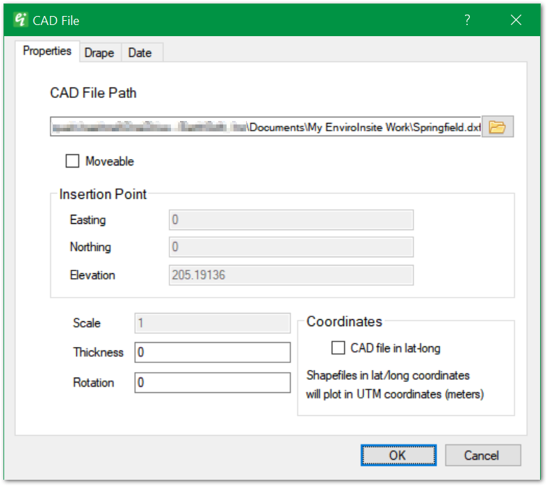
CAD File Path – Click Browse button to select a CAD file.
Moveable – Check to allow inserted CAD file to be moved in the view by dragging the string with the mouse.
Insertion Point – Insertion point coordinates at center of CAD plotted area.
Scale – Enter horizontal scale factor (1 for no scaling).
Thickness – Enter vertical line thickness.
Rotation – Enter rotation about center point in degrees clockwise.
Coordinates > CAD file in lat-long – Check if CAD file is in latitude-longitude coordinates, in which case they will be converted to specify document coordinates (i.e., UTM or State Plane).
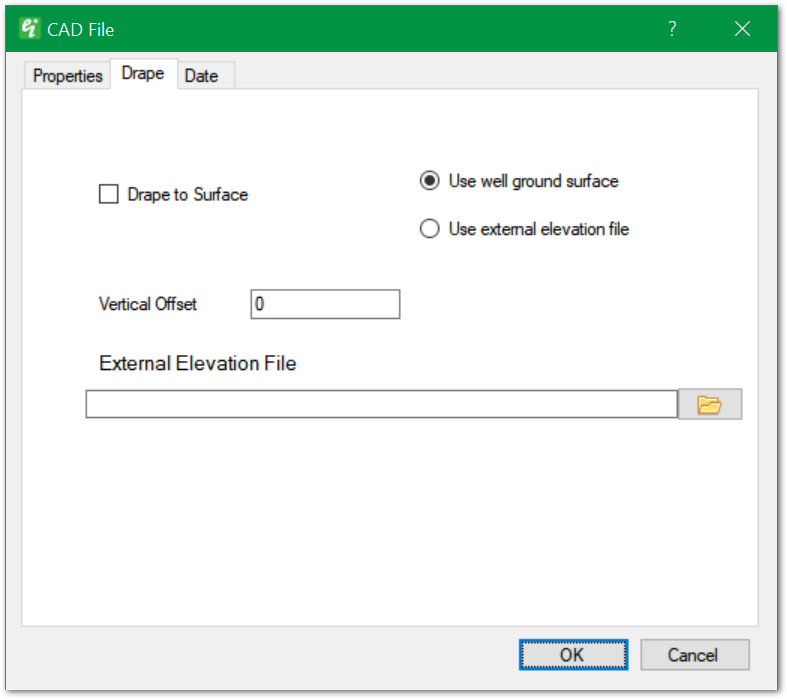
Drape to Surface – Check to cause CAD file to drape to defined surface.
Use well ground surface / Use external elevation file – Two options are available for draping a CAD file to a surface. When using well ground surface, EnviroInsite will use the Surface Elevation field of the Wells table to define the surface on which the image is draped. Alternatively, an external elevation file can be used to define the surface. The external elevation file should be an ASCII file, either comma or space delimited. Each record should have the location (X, Y) and the surface elevation (Z) on which the CAD image is to be draped.
Vertical Offset – Enter vertical offset relative to calculated drape value at each point.
External Elevation File – Click Browse button to select external elevation file. The contents of file are only used if "Use external elevation file" has been selected.